Delve into the process of optimizing your design for injection molding, ensuring quality and efficiency through understanding material selection, part design, tooling fabrication and production practices.
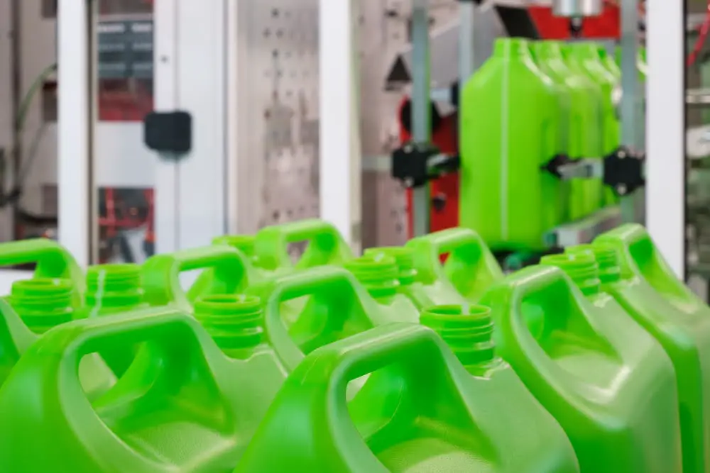
Injection molding is a widely used manufacturing process for producing parts from plastic materials. In this process, molten plastic is injected into a mold, which is then cooled to solidify the material in the shape of the mold cavity.
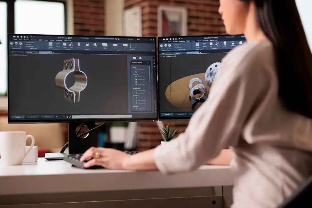
Designing for injection molding involves several key considerations to ensure the produced parts meet the desired quality standards. These include the part design, material selection, mold design, and process parameters.
Understanding these factors is crucial to optimizing the injection molding process, reducing costs, and improving product quality. This article will provide a comprehensive guide on how to design for injection molding, covering all the essential details you need to know.
Key takeaways:
- Proper material selection for injection molding based on functionality and appearance.
- Design factors to consider such as part complexity, anticipated stresses, and production scale.
- Importance of selecting a suitable parting line to ensure quality and minimize flash formation.
- Benefits of incorporating draft angles in the design to ease ejection and improve surface quality.
- Strategies for managing thick areas, including uniform wall thickness, coring, and ribbing.
Understanding Injection Molding Process
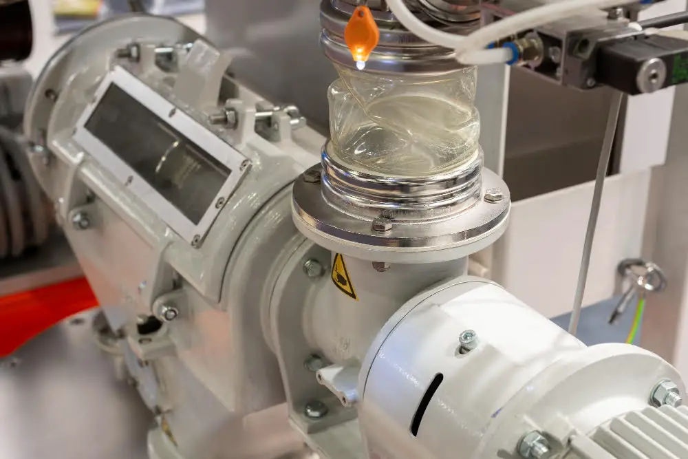
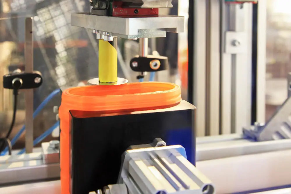
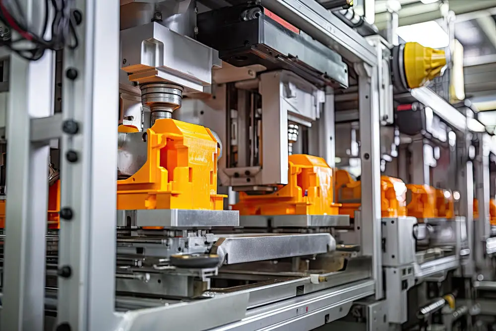
Fundamentally, injection molding comprises several crucial steps. Initially, a heat-softened plastic material is injected under high pressure into a relatively cool mold. Cooling down, the plastic hardens into the shape of the mold, forming the desired part.
Key elements to remember in this process include:
- The Choice of Plastic: Varying on factors such as strength, flexibility, and color, the type of plastic used makes a significant difference in the end product.
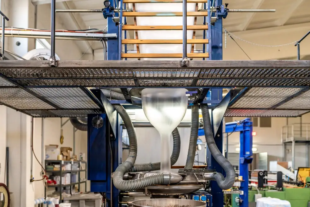
- The Injectable Material: This could be in the form of pellets or granules, which are then heated until they reach a liquid state, ready for injection into the mold.
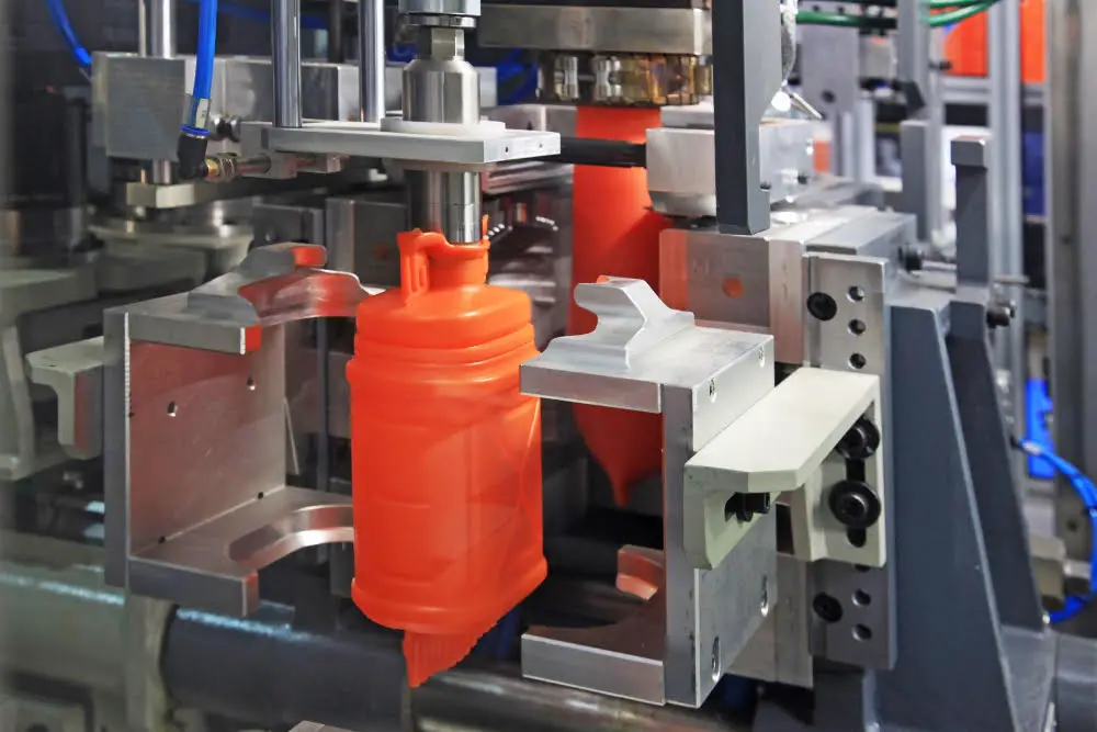
- The Mold: Typically composed of metal, the mold is precision-machined to form the features of the desired part.
- The Injection Process: The material gets injected into the mold, then cools and solidifies, taking the shape of the mold.
After the cooling, the mold opens, and the finished part is ejected. The overall cycle time can vary depending on the part’s complexity.
Material Selection for Injection Molding
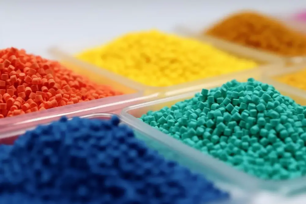
Material selection can greatly impact the end product’s functionality, appearance, and the overall manufacturing process. Keep the following in mind:
Selecting thermoplastic resins provides many benefits due to their durability and resistance to high temperatures.
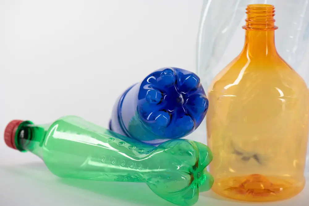
Plastic polymers, such as ABS, Polypropylene, and Polystyrene, offer great flexibility and strength, ideal for a variety of applications.
Consider the intended use of the product when choosing materials. For example, if the end product will be exposed to the outdoors, ultraviolet (UV) resistant materials are necessary.
Factor in the melt flow rate of the intended material. The higher the rate, the easier the material flows during injection, which can be beneficial for intricate designs.
Understand the specific design needs of your product. Certain materials lend themselves better to achieving high-gloss finishes, texture, or high strength.
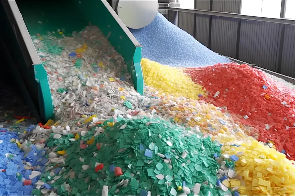
Keep in mind environmental impacts. Some materials are more easily recycled than others, improving the overall sustainability of the end product.
Consider cost, as material prices vary significantly. Therefore, striking a balance between cost-effectiveness and functionality is essential.
Essential Design Factors for Injection Molding
To begin, consider the geometrical complexity of the part to be produced. Mismanaged complex shapes can affect how evenly the plastic fills the mold, potentially compromising structural integrity.
Next, evaluate the anticipated function and physical stresses. Durable polymers may be required for parts under heavy use, while lighter plastic types might be more suitable for cosmetic components.
Also, think about the production run scale. Certain design strategies may be more practical for high-volume, low-cost production and less so for smaller runs or highly specialized applications.
Furthermore, anticipate post-production processes. Some designs may require secondary operations, such as assembly or finishing, which should be factored into the initial design plan.
Lastly, consider the type of polymer to be used, as different materials behave differently when heated and cooled. This can hugely impact both the design and manufacturing process.
Selecting a Parting Line in Injection Molding
The parting line largely determines the quality and finish of the molded part. Here are some crucial ideas and guidelines:
1. Positioning of the Part: The parting line should ideally be along the edge of the part, where it can have the least significant impact on the part’s appearance.
2. Symmetry Matters: If the part has symmetry, align the parting line to this symmetry plane. It simplifies part design and molding process.
3. Complex Geometry Considerations: For parts with a complex geometry, the parting line path may need to be split or segmented to maintain control over the part’s aesthetics and functionality.
4. Consideration for Ejecting: The line should also consider the ejection system to prevent part deformation during the ejection process.
5. Minimizing Flash Formation: A well-planned parting line can minimize flash, the excess material that seeps between the mold halves during the injection process.
6. Surface Texture and Tolerance: Consideration of the surface texture and tolerance in parting line location can reduce the visibility of the line on a finished product.
Remember, the decision of the parting line location calls for a crucial balance between the part’s function, appearance, and the manufacturability. An effective design review with your injection molder can help determine the optimal line location.
Advantages of Draft in Injection Molding
Drafts, the slight angles included in the walls of a part, are crucial in the injection molding process. They provide distinct advantages, such as:
- Easier Ejection: A draft prevents the part from scratching or catching onto the mold during ejection. It aids a seamlessly smooth transition as the finished part exits the mold.
- Improved Surface Quality: Drafts offer a slick surface which reduces the drag at the time of removal. This results in parts with smooth, high-quality exterior finishes.
- Enhanced Mold Lifespan: Less resistance during ejection means less wear on the mold. Drafts thus protect against damage, extending the life of the mold.
- Efficient Production: By minimizing resistance, drafts allow for faster cycle times and greater productivity.
They can be incorporated into the design by using CAD software. It’s preferable to apply the draft as early as possible in the design phase to maximize these benefits. Remember, even a small draft angle can significantly improve the molding process. The exact draft angle will vary by part and material, but a general rule of thumb is a minimum of 1 degree of draft for every 1 inch of vertical cavity depth.
Managing Thick Areas in Injection Molding
Managing thick areas in injection molding is crucial for a successful design. These areas can cool slower than the rest of the part, generating stress and potential warpage. Let’s explore the ways this can be handled.
Emphasize uniform wall thickness. In an ideal design, the wall thickness of the molded part should be uniform. This facilitates even cooling and minimizes stresses.
Consider coring. If avoiding a thick area is impossible, coring might be a solution. Coring involves removing material from the inside of the thick area, creating a hollow section and reducing thickness.
Implement ribs. In some circumstances, ribs are used to increase part strength without adding solid thick sections. They should be designed with a thickness of 0.5-0.75 times the adjoining wall to avoid problems.
Avoid abrupt transitions from thick to thin walls. Such transitions can cause stress concentration and potential failure of the part. Softer transitions are preferable.
Apply the right cooling methods. Sometimes, the answer lies not in the design, but in the processing. Using additional cooling methods can help control the temperature within thick areas and prevent deformations.
Remember, properly managed thickness is essential for mold performance, part quality, and overall efficiency of the injection molding process.
Use of Coring and Ribbing in Injection Molding Design
Coring is a strategic mechanism used in the injection molding process. It’s essentially hollowing out the thick sections of part design, thus reducing cooling time, minimizing material usage, curtailing cycle time, and boosting the structural stability of the part.
In contrast, ribbing serves as fortification for thin-walled parts used in injection molded designs. The addition of ribs enhances the bending stiffness of the part without increasing the wall thickness, thus maintaining the mold’s efficiency.
For successful application, these key ideas should be considered:
- Coring should be done conservatively, too much might compromise the part’s structural integrity.
- The rib’s height shouldn’t exceed three times the wall’s thickness to prevent sinking effects.
- Maintain uniform wall-thickness when coring or ribbing to ensure even cooling and prevent warping.
- Ribs should be spaced adequately apart, preferably two times the wall thickness.
- Keep the rib base’s thickness at around half of the main wall’s thickness to avoid undesired thick sections.
- Use draft angles with ribs and cores to aid removal from the mold.
Keeping these points in mind will direct towards a more efficient usage of coring and ribbing strategies.
Emphasizing Uniform Wall Thickness in Injection Molding
Maintaining uniform wall thickness in injection molding designs helps optimize the production process. However, achieving this can be somewhat complex. Here are the key points to consider:
Enhanced Material Flow: A uniform thickness encourages a steady, uninterrupted flow of the polymer during the molding, reducing chances of material stagnation, premature cooling or warping.
Minimizing Sink Marks: Non-uniform thickness often results in sink marks. These are indentations that occur when the inner material cools and shrinks faster than the outer material. To avoid this, consistency in wall thickness is encouraged.
Mitigating Shrinkage Variations: Similarly, uniform thickness helps manage shrinkage variations in the molding. With consistent thickness, the whole design cools at a similar rate thereby maintaining the intended final dimensions.
Reducing Stress Concentrations: By maintaining a uniform wall thickness, the part experiences fewer stress concentrations. This lowers the likelihood of producing components with weak points that may break or fail over time.
Cooling Time Reduction: Uniform thickness also means that the part’s cooling time is reduced. Thicker sections take longer to cool, extending the cycle time. When walls are of the same thickness, cooling time is drastically reduced, making the process more efficient.
By keeping these points in mind when designing for injection molding, one can avoid problems like warping, sink marks, premature cooling, and stress concentrations, while also speeding up the production process. Note that the recommended wall thickness would vary depending on the material used and the specific application of the molded part. Always consult with material data sheets or a molding expert when in doubt.
Role and Integration of Radii in Injection Molding Design
Understanding the integration of radii is an essential part of designing for injection molding. The use of radii aids in streamlining the flow of plastic throughout the mold, reducing the likelihood of imperfections.
Radii can complement specific design elements: They enhance the structural integrity by alleviating stress concentrations which occur on sharp corners. This is crucial to prevent brittle failures, particularly for polymers susceptible to cracking.
Size matters: There’s a delicate balance to strike – too large a radius could compromise the fit of the component, whilst a smaller radius may exert stress. Taking careful consideration of the precise measurements required is pivotal.
Maintaining consistency: Employing the same radius at all corners aids in uniform shrinkage, reducing potential warping or distortion.
Smooth Transitions: Creations of transitions from thick to thin areas should be as smooth as possible to enhance the flow of plastic, thus reducing the risk of sink marks or voids.
Practical Application: For tangible implementation, the design software will enable the integration of radii into the design. These insights should be kept in mind, especially during the creation of the dimensional design.
Building Bridges: Even when designing for overmolding and undercuts, the role of radii should not be ignored. Bridging sharp corners with precisely engineered radii can simplify the injection molding process.
Addressing Injection Molding Design Challenges
There are several ways to address the common challenges that arise in injection molding design.
One crucial step involves the optimization of wall thickness. It’s not uncommon for inconsistent wall thickness to cause issues such as warping, sinks or voids. To avoid these issues, aim for uniform thickness wherever possible.
Controlling the gate location can also significantly influence the quality of the final product. Positioning gates effectively ensures that the right amount of material enters the mold at the correct time, thus preventing short-shot or overpacking situations.
Another common challenge involves eliminating undercuts, which can make the ejection of the molded part difficult. Through clever design strategies like collapsible cores or side-actions, undercuts can be managed effectively.
Remember to address the issue of weld lines too. These are formed where two melt fronts meet during the molding process and, if not properly managed, can weaken the overall structure of the molded part. The problem can be solved by carefully planning the gate location and part geometry.
Lastly, using simulation software can be beneficial. It helps predict potential problems in the design phase, such as material flow issues or cooling inconsistencies, and allows you to adjust the design accordingly before production begins.
FAQ
How do you calculate injection molding shot size?
To calculate injection molding shot size, you divide the weight of the material used (in grams) by its density (in g/cm3), such as in the example where a 40.6g weight and a 1.52g/cm3 density results in a shot size of 43.4mm.
What is the rule of thumb for injection molding?
The rule of thumb for injection molding is to use 1-degree of draft per inch of depth, with sufficient thickness to allow cutter penetration.
What factors influence the cooling time in injection molding?
The cooling time in injection molding is influenced by factors such as the thickness of the part, the type of plastic used, the mold temperature, the temperature of the melted polymer, and the design of the cooling system.
How does the type of polymer affect the injection molding process?
The type of polymer affects the injection molding process by determining the melting point and cooling rate, thus influencing the mold design, cycle time and the final properties of the molded part.
What are the key considerations for choosing the mold material for injection molding?
The key considerations for choosing mold material for injection molding include thermal conductivity, wear resistance, ability to withstand high pressure, machinabilty, and cost efficiency.
Related Reading
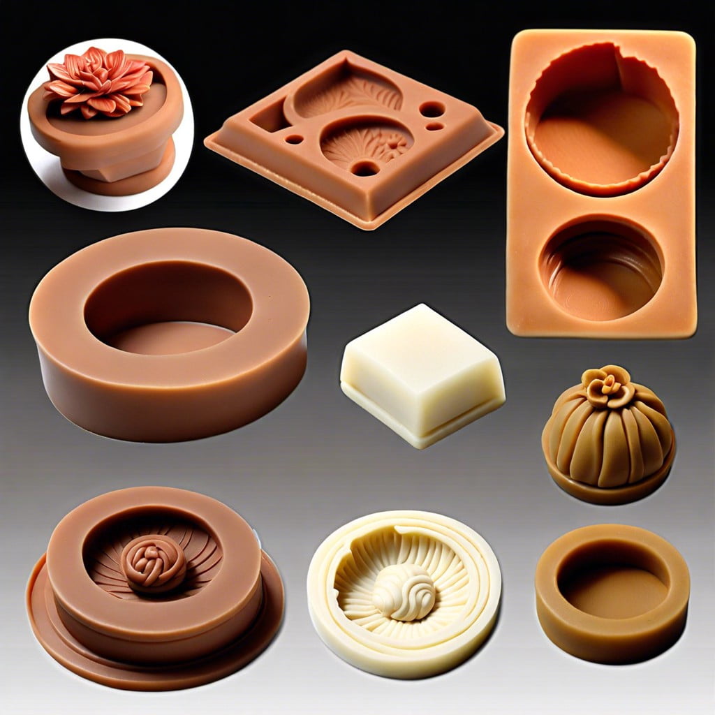 Polymer Clay Molds: How to Create and Use Them Effectively
Polymer Lower: Understanding Its Uses and Benefits in Modern Applications
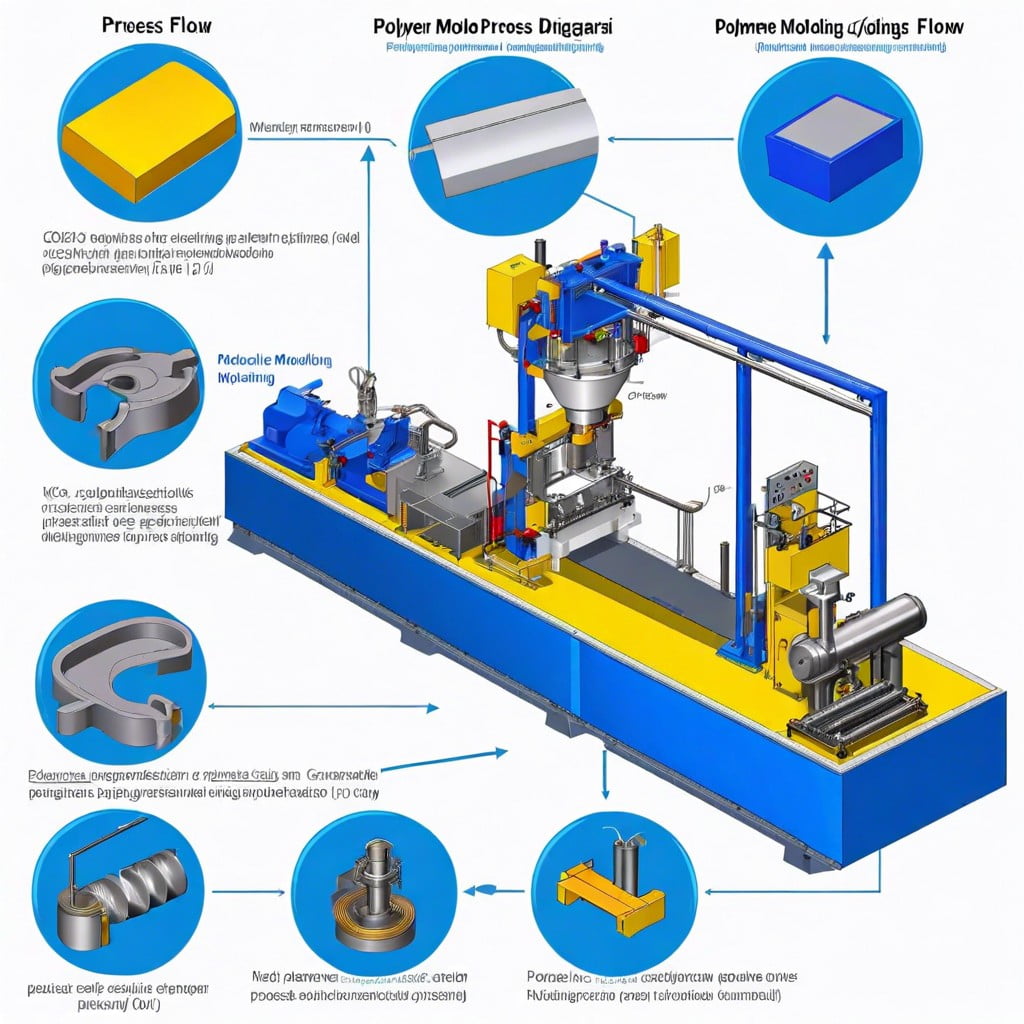 Polymer Molding: Understanding the Process and Its Applications
 How to Find Plastic Extrusion Clients: A Comprehensive Guide to Acquiring Business Leads
 How to Make Plastic Fence Extrusion: A Comprehensive Guide for Beginners
Recap